
leave a message
If you are interested in our products and want to know more details,please leave a message here,we will reply you as soon as we can.
A vertical solar mounting system holds photovoltaic modules upright — usually at 90 degrees to the ground — instead of tilting them toward the sun. On sites that fight snow, fallen leaves, dust, narrow plots or a shortage of usable land, that single change in geometry solves problems that conventional tilted racking cannot. This guide explains how a solar vertical mounting system is engineered, where vertical bifacial solar panels make the most sense, which specifications to demand, and how to avoid the design mistakes that quietly cost yield.
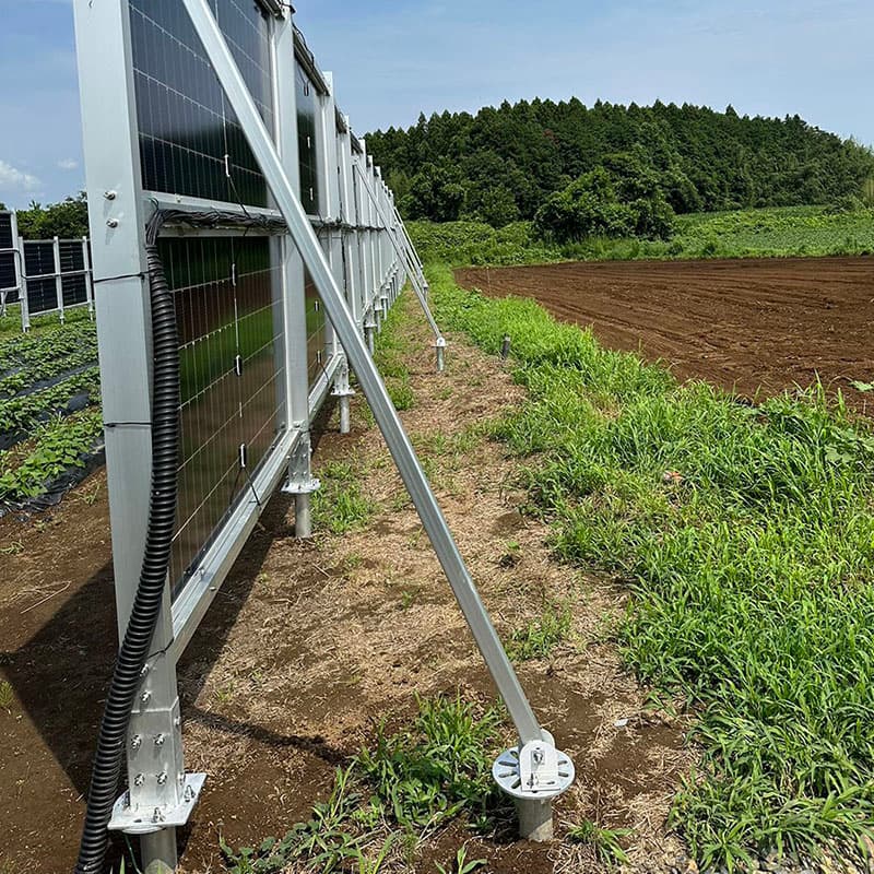
A vertical solar mounting system is a ground-mounted structure that clamps modules in a near-vertical plane, normally facing east on one side and west on the other, or as a single south-facing wall. Galvanized steel posts are driven or screwed into the ground, horizontal rails carry the module frames, and mid-clamps and end-clamps lock each panel in place. Because the array stands upright, it occupies a narrow strip of land instead of a wide tilted footprint: a two-metre-high array may need less than 1.5 m of depth including service access.
The system shown here uses a double-tier layout that doubles capacity on the same post line. Module specification is unlimited, so the structure can be configured around 182 mm, 210 mm or custom frameless modules without changing the foundation plan — a practical advantage for EPC contractors who source modules from more than one supplier.
Every vertical solar panel mount shares the same load path: module frame to clamp, clamp to rail, rail to post, post to soil. What separates a good system from a cheap one is how carefully each of those four connections is engineered for wind uplift and frost movement.
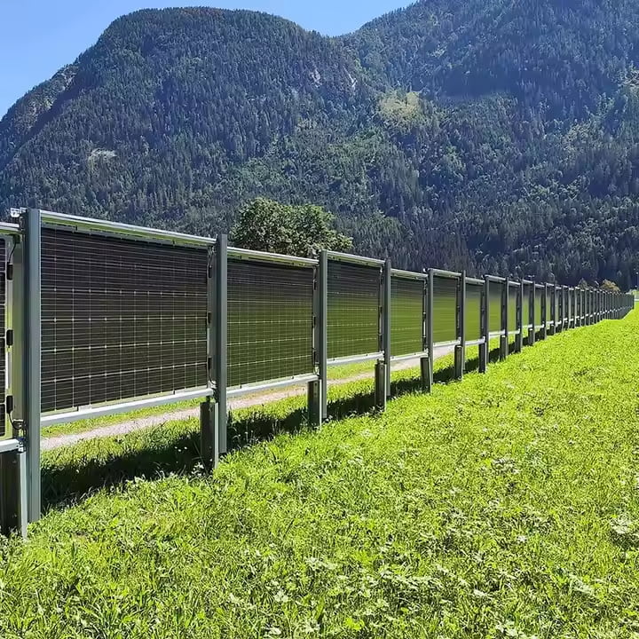
Vertical mounting is most valuable with bifacial modules. One face receives direct light in the morning and the other in the afternoon, while both faces collect reflected light from snow, sand, gravel, white concrete or light-coloured ground. The result is a flatter daily production curve with pronounced morning and evening shoulders instead of a single midday peak.
For grid operators and commercial self-consumers, that shape is often worth more than a higher noon output. A vertical array generates earlier and later in the day, closer to the demand curve, and it avoids the midday clipping that forces oversized inverters on conventional arrays. On high-albedo sites — snow, white gravel, light concrete — the rear-side gain can be substantial, which is why bifacial vertical solar is now a standard configuration rather than a niche experiment.
One of the fastest-growing applications is a solar fence mounting system: a vertical array built along a property line, highway edge, railway corridor or industrial fence. Instead of consuming productive farmland or clearing new ground, the structure uses a boundary that already exists. Because the modules stand vertically, the fence remains a fence — it defines the perimeter, slows ground-level wind and adds generation without shading the field behind it. For developers who cannot expand a site, the fence line alone can add hundreds of kilowatts of capacity.
The same logic applies inside a plant. A vertical ground mount along a car park edge, a storage yard or a security line turns unused vertical space into an asset, and the low, narrow profile keeps forklift and truck routes clear.
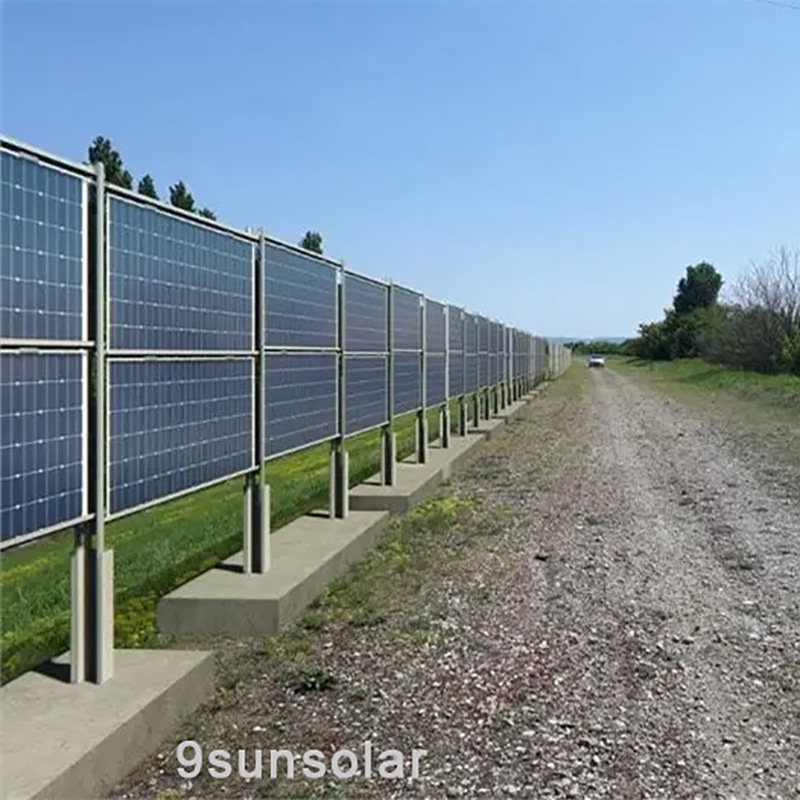
A vertical array trades one load case for another. Wind uplift on a vertical plane is high, so the structure must be designed for the project’s basic wind speed rather than a generic figure. The reference specification for this system is a ground foundation, AL6005-T5 aluminium alloy rails and clamps, Q235 galvanized steel posts, a 46 m/s wind load, a 1.4 kN/m² snow load and a 10-year quality assurance.
Height above the local snow line is the detail most often missed. The bottom edge should stay clear of the maximum expected snow depth plus drift; otherwise the array becomes a snow fence, and the lower modules carry loads the structure was never asked to take. Row spacing needs the same care. Vertical arrays cast long shadows in low-sun months, so the east-west distance between parallel lines must come from a shading study, not a rule of thumb.
An AL6005-T5 aluminium alloy rail carries the module load without the weight of steel, while Q235 galvanized steel posts provide the stiffness and driveability that ground foundations require. The combination stays light enough to install by hand yet stiff enough to resist 46 m/s wind. Stainless fasteners and isolation washers prevent galvanic corrosion at the aluminium-steel interface — a small detail that separates a 25-year structure from a maintenance problem. The 10-year quality assurance covers the structural components under normal site conditions, and the open profile keeps inspection simple.
Land use. A tilted array needs deep rows and wide inter-row spacing. A vertical system needs a narrow strip, so it wins whenever land is scarce, expensive or irregular.
Energy per module. A tilted array at the optimal angle still produces more kilowatt-hours per panel in most climates. Vertical mounting competes on energy per hectare, not per module.
Energy per hectare. Because vertical rows can be packed far more densely, total site output is often comparable — and higher on high-albedo or snow-prone sites.
Snow and debris. Vertical wins clearly. There is nothing to clear after a snowfall, and leaves do not settle.
Maintenance. Vertical modules are easier to inspect and clean, and there is no need for snow-removal equipment or roof access.
Cost per kilowatt. Fewer posts and less land per kilowatt usually offset the extra module area, particularly where land acquisition is the dominant cost.
A vertical array is quick to erect when the sequence is respected. Skipping the survey or the torque check is what causes callbacks later.
Per module, usually yes in a sunny, low-latitude climate. Per hectare, often no: vertical rows can be packed much more densely, and bifacial gain from ground reflection narrows the gap. In snowy or high-albedo regions a vertical solar mounting system can match or exceed a tilted array on annual site yield.
East-west facing is the standard for bifacial vertical mounting because it captures both the morning and afternoon sun and gives each face its own production window. A single south-facing vertical wall is used where the array follows a boundary or building line and only one face is practical.
Yes. Snow slides off a vertical surface instead of accumulating, and this system is specified for a 1.4 kN/m² snow load. The critical detail is keeping the bottom edge above the expected snow depth so drifting snow cannot bridge the gap and load the lower modules.
It is one of the best configurations for it. The narrow footprint leaves most of the field in full sun, machinery can pass between rows, and the low wind profile reduces stress on crops. Many projects combine a vertical ground mount with grazing or strip cropping.
The reference design is rated for a 46 m/s wind load — roughly 165 km/h — with Q235 galvanized steel posts and AL6005-T5 aluminium rails. Projects in higher-exposure locations should always be recalculated against the local code rather than relying on the catalogue figure.
9Sunsolar engineers vertical solar mounting systems around your site, not around a catalogue page. Send us your land layout, snow depth, wind speed and module datasheet, and our team will return a foundation plan, a bill of materials and a configuration that keeps the bottom edge clear, the row spacing correct and the structure inside its rated loads. Whether you are building a solar fence mounting system along a boundary or a multi-row vertical ground mount on open land, we will quote the complete structure — posts, rails, clamps and fasteners — with a 10-year quality assurance.
Signup our newsletter to get update information, promotion and insight.


 IPv6 network supported